CLICK & FLOOR INSTALLATION GUIDE
I. GENERAL PREPARATIONS
TOOLS REQUIRED:
Spacers, rubber mallet, ruler, pencil, tape measure, utility knife.
– Prior to installation, inspect material in daylight for visible faults/damage, including defects or discrepancie in color or shine; check the edges of the flooring for straightness and any damage. No claims on surface defects will be accepted after installation.
– It is preferable to lay boards perpendicular to the window, following the direction of the main source of light. For the best result, make sure to always work from 3 to 4 cartons at a time, mixing the planks during the installation.
– Check if subfloor/site conditions comply with the specifications described in these instructions. If you are not satisfied, do not install, and contact your supplier.
– Flooring products can be damaged by rough handling before installation. Exercise care when handling and transporting these products. Store, transport and handle the flooring planks in a manner to prevent any damage. Store cartons flat, never on edge.
– Flooring products can be heavy and bulky. Always use proper lifting techniques when handling these products. Whenever possible, make use of material-handling equipment such as dollies or material carts. Never lift more than you can safely handle; get assistance.
– Calculate the room surface prior to installation and plan an extra 5-10% of flooring for cutting waste.
– The environment where the flooring is to be installed is critically important with regard to successful installation and continued performance of the flooring products. The flooring is intended to be installed in interior locations only. These interior locations must meet climatic and structural requirements as well.
– In most cases, this product does not need to be acclimated. However, if the boxes of flooring were exposed over 2 hours to extreme temperatures under 50°F / 10°C or over 104°F / 40°C within the 12 hours before the installation, acclimation is required. In this case, keep the boards in room temperature for at least 12 hours in unopened package before you start the installation. The room temperature must be maintained consistent between 70-80°F / 20-25°C before and during the installation.
– Flooring should only be installed in temperature-controlled environments. It is necessary to maintain a constant temperature of 70-80°F / 20-25°C before and during the installation. Portable heaters are not recommended as they may not heat the room and subfloor sufficiently. Kerosene heaters should never be used.
– After installation, make sure that the flooring is not be exposed to temperatures less than 50°F / 10° C or greater than 120°F / 50°C.
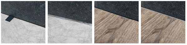
– For surfaces over 400sqm, over 20m long or in the case of a surface where there has to be a transition from Click&Floor to a different floor tile, we recommend using T profiles taking care of the expansion joints (same joint that the perimeter joint)
II. SUBFLOOR INFORMATION
– The flooring can be installed over most existing hard surface floor coverings, provided that the existing floor surface is clean, flat, dry, securely fastened, structurally sound and level to 3/16” / 5 mm within 10 ft / 3 m.
– The substrate should not slope more than 1” / 25 mm per 6 ft / 2 m in any direction.
– Depressions, deep grooves, expansion joints and other subfloor imperfections must be filled with patching & leveling compound.
– Substrates must be free from excessive moisture or alkali. Remove dirt, paint, varnish, wax, oils, solvents, any foreign matter and contaminates.
– Do not use products containing petroleum, solvents or citrus oils to prepare substrates as they can cause staining and expansion of the new flooring.
– Although this floor is waterproof, it is not aimed to be used as a moisture barrier. The concrete moisture vapor emissions should not exceed 8 lb / 3.63 kg (ASTM F1869) / 90 % RH (ASTM F2170) with a PH limit of 9 / max 2.5 % moisture content (CM method).
– This product is also not to be installed in areas that have a risk of flooding such as saunas or outdoor areas.
– Existing sheet vinyl floors should not be heavily cushioned and not exceed more than one layer in thickness. Soft underlayment and soft substrates will diminish the products inherent strength in resisting indentations.
WOOD SUBFLOORS
– If this flooring is intended to be installed over an existing wooden floor, it is recommended to repair any loose boards or squeaks before you begin the installation.
– Nail or screw every 6” / 15 cm along joints to avoid squeaking.
– Basements and crawl spaces must be dry. Use of a 6 mil / 0.15 mm poly-film is required to cover 100 % of the crawl space earth.
– We recommend laying the flooring crossways to the existing floorboards.
– All other subfloors – Plywood, OSB, particleboard, chipboard, wafer board, etc. must be structurally sound and must be installed following their manufacturer’s recommendations.
CONCRETE SUBFLOORS
– Existing concrete subfloors must be fully cured, at least 60 days old, smooth, permanently dry, clean, and free of all foreign material such as dust, wax, solvents, paint, grease, oils, and old adhesive residue. Curing agents and hardeners could cause bonding failure and should not be used.
– We recommend using a minimum 6 mil / 0.15 mm poly-film as a moisture barrier between the concrete subfloor and the flooring.
DO NOT INSTALL OVER
– Any type of carpet.
– Existing cushion-backed vinyl flooring.
– Floating floor of any type, loose lay, and perimeter fastened sheet vinyl.
– Hardwood flooring / wood subfloors that lay directly on concrete or over dimensional lumber or plywood used over concrete.
IMPORTANT NOTICE
In-floor Radiant Heat: Flooring can be installed over 1/2” / 12 mm embedded radiant heat using the floating method.
Maximum operating temperature should never exceed 85°F / 30°C. Use of an in-floor temperature sensor is recommended to avoid overheating.
– Turn the heat off for 24 hours before, during and 24 hours after installation when installing over radiant heated subfloors.
– Before installing over newly constructed radiant heat systems, operate the system at maximum capacity to force any residual moisture from the cementitious topping of the radiant heat system
– Make sure that the temperature in the room is maintained consistent between 70-80°F / 20-25°C before and during the installation.
– Floor temperature must not exceed 85°F / 30°C.
– Once the installation has been completed, the heating system should be turned on and increased gradually (5-degree increments) until returning to normal operating conditions
– Refer to the radiant heat system’s manufacturer recommendations for additional guidance.
Warning
Electric heating mats that are not embedded into the subfloor are not recommended for use underneath the floors. Using electric heating mats that are not embedded and applied directly underneath the floors could void the warranty for your floor in case of failure. It is best to install the flooring over embedded radiant floor heating systems and adhere to the guidelines listed above.
III. INSTALLATION
– Remove baseboard, quarter-round moldings, wall base, appliances and furniture from room. For best results, door trim should be under-cut to allow flooring to move freely without being pinched. After preparation work, sweep and vacuum the entire work area to remove all dust and debris.
– With a floating floor, you must always ensure you leave a 1/4” / 6 mm gap between walls and fixtures such as pillars, stairs, etc. These gaps will be covered with trim moldings after the floor is installed.
– Whenever possible, plan the layout so that the joints in the planks do not fall on top of joints or seams in the existing substrate. The end joints of the planks should be staggered a minimum of 8” / 20 cm apart. Do not install over expansion joints. Avoid installing pieces shorter than 12” / 30 cm at beginning or end of rows.
– Do not install your kitchen cabinets directly over your floor. The floor’s quality can be guaranteed as long as the floor can move freely.
– Decide the installation direction. It is recommended to install the boards perpendicular to the window following the direction of the main source of light.
– Measure the area to be installed: The board width of the last row shall not be less than 2” / 50 mm. If so, adjust the width of the first row to be installed. In narrow hallways, it is recommended to install the floor parallel to the length of the hall.
– UNDERLAY: If the floor does not have a pre-attached underlayment, an additional underlayment is recommended in order to improve acoustic performance and absorb some irregularities on the substrate. Best results can be expected with an underlayment of 0.04” / 1mm to max 0.06” / 1.5 mm thickness with a high density (>11.2 lbs / ft3 / >180 kg /m3) and high compressive strength (>200 kPa) that supports the click system during daily use. Underlayments with a low density and an inadequate compressive strength could damage the locking mechanism and will void warranty.
– If the floor has a pre-attached underlayment, the use of an additional underlayment could damage the locking mechanism and will void warranty.
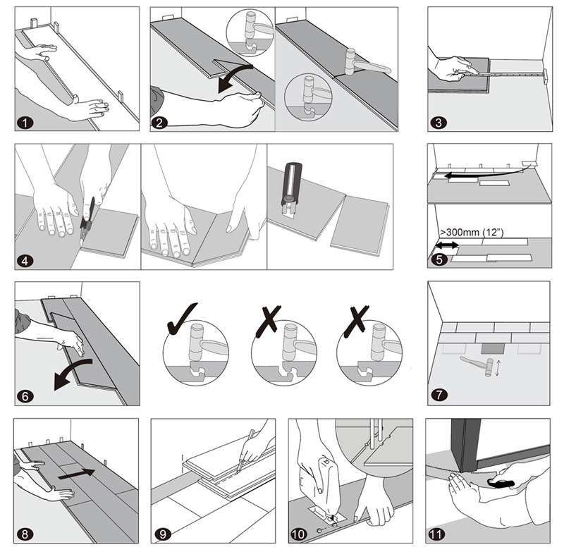
1. First row, first plank
After thoroughly cleaning the subfloor, you should begin laying from left to right. Position the first plank so that grooved edge is facing you. Place the floorboard 1/4” / 6 mm from the left wall. Use spacers between the wall and the floorboard.
2. First row, second plank
Drop the plank and gently tap down the end with a rubber mallet so it firmly locks into the previous plank until both are at the same height. Make sure both planks are perfectly aligned. It is crucial that after the short edges of two connecting planks are correctly aligned, and the rubber mallet contacts the plank in the area directly above the short edge, allowing for a correct locking. Note: Tapping the area close to the short edge, but not directly above it, may result in permanent damage to the joint. Continue installing the first row until you reach the wall on the right.
IMPORTANT
If you notice both planks aren’t at the same height or are not well locked together, please follow the disassembling instructions at the bottom of the page, disassemble and check if any debris stuck inside the lock is obstructing. Failure to properly line up the end joint and attempting to force it in while out of alignment could result in permanent damage to the end joint.
3. First row, last plank
At the end of the first row, leave an expansion gap of 1/4” / 6 mm to the wall and measure the length of the last plank to fit.
4. To cut the plank
Use a simple utility knife and ruler, and with the top side facing up, cut heavily and several times on the same axis. The knife will not go through the surface but make a deep cut. You can then lift one half of the plank using your other hand to hold down the second placing it very close to the cut. The plank will split naturally.
5. Second row, first plank
Start the second row with the leftover cut part of the last plank of the previous row. This small plank should measure at least 12” / 30 cm. Otherwise, cut a new plank in half and use it to begin the second row. The end joints of each adjoining row should not be closer than 8” / 20 cm to each other. Whenever practical, use the piece cut from the preceding row to start the next row.
6. Second row, second plank
Click the long side of the plank into the previous row and place it tight to the short end of the previous plank with an angle of 25-30°. Drop the plank and gently tap on the end with a rubber mallet so it firmly locks into the previous plank until both are at the same height. Make sure both planks are perfectly aligned.
7. After finishing the installation of every row
Use scrap pieces and a small hammer or rubber mallet to gently tap the planks into the click of the previous row to make sure they are tightly clicked together and make sure there is no gap between the long side of the planks installed. Any gapping can compromise the whole installation.
8. Tip
After the first 2-3 rows of planks are installed, they should be checked with a string line to ensure that rows are still running straight. If they are not, it could be that the starting wall has some irregularities that caused bowing in the installation. If so, the starting row of planks may have to be scribed and re-trimmed to account for any unevenness in the wall. This can be done without having to disassemble the beginning rows.
9. To lay the last row
Position a loose board exactly on top of the last row laid. Place another board on top, with the tongue side touching the wall. Draw a line along the edge of this boards, to mark the first board. Cut along the edge of this board to mark the first board. Cut along this line to obtain the required width. Insert this cut board against the wall. The last row should be at least 2” / 50 mm wide. The spacers can then be removed.
10. Holes for pipes
Measure the diameter of the pipe and drill a hole that is 1/2” / 12 mm larger. Saw off a piece as shown in the figure and lay the board in place on the floor. Then lay the sawed-off piece in place.
11. Door molding and skirting
Lay a board (with the decorative side down) next to the door molding and saw as shown in the figure. Then slide the floorboard under molding.
IV. FINISHING THE INSTALLATION
Replace molding or wall base, allowing slight clearance between the molding and the planks. Nail the molding to the wall surface, not through the flooring. At doorways and at other areas where the flooring planks may meet other flooring surfaces, it is preferable to use a “T” molding, or similar, to cover the exposed edge but not pinch the planks. Leave a small gap between the planks and the adjoining surface.
V. MAINTENANCE
– Sweep or vacuum daily using soft bristle attachments.
– Clean up spills and excessive liquids immediately.
– Damp mop as needed and use cleaners recommended for vinyl flooring.
– The use of residential steam mops on this product is allowed. Use at lowest power with a suitable soft pad, and do not hold a steam mop on one spot for an extended period of time (longer than 5 minutes). Refer to the steam mop’s manufacturer instructions for proper usage.
– Use proper floor protection devices such as felt protectors under furniture.
– Place a walk-off mat at outside entrances to reduce the amount of dirt brought into your home. Do not use mats with a latex or rubber backing since these backings can cause permanent discoloration.
– Do not use abrasive cleaners, bleach or wax to maintain the floor.
– Do not drag or slide heavy objects across the floor.
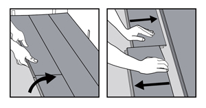
VI. DISASSEMBLING
Separate the whole row by lifting it up delicately at an angle. To separate the planks, leave them flat on the ground and slide them apart. If planks do not separate easy, you can slightly lift up the planks (5°) when sliding them apart.
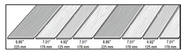
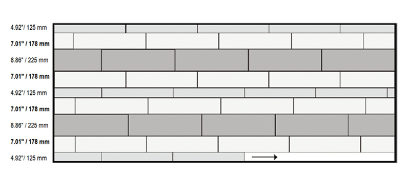
SPECIFIC FOR MULTI NOGAL SERIES
III. INSTALLATION
Note: A 7” / 178 mm wide plank MUST be used in every other row. This sequence must be followed throughout the entire installation.
SPECIFIC FOR CHEVRON SERIES
III. INSTALLATION
ATTENTION
The letter “L” or “R” marked on the back of each chevron plank indicate two different profiling directions. There is the same number of L planks and R planks in each box. Please pay attention to the markings and always install them paired together. In below instructions, L planks are represented in white, R marked planks are represented in grey.
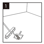
The subfloor should be even, dry, clean. Carpet staples or glue residues must be removed, and the floor must be clean to ensure proper installation.
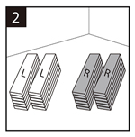
Separating into distinctive piles will make it easier to find the correct plank should the L or R markings be cut off.
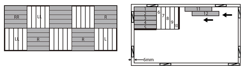
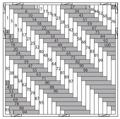
METHOD 1 – BLOCK PATTERN
– This installation method consists in grouping 5 planks with the same profiling together. You can then start staggering your spacers across your wall, leaving a 1/4” / 6 mm expansion gap with the wall.
– Start in the left corner opposite from the main entrance with an R plank, put the tongue sides against the wall, and follow the sequence on the image (Refer to the clicking tips on the bottom of the page). Always leave a 1/4” / 6 mm expansion gap with the wall.
IMPORTANT: We recommend applying a high-grab high-shear hard-setting adhesive inside the locking system at the short side of the planks for additional engagement, avoid using adhesive excessively and be sure to immediately wipe away any excess that comes out to the floor’s surface.
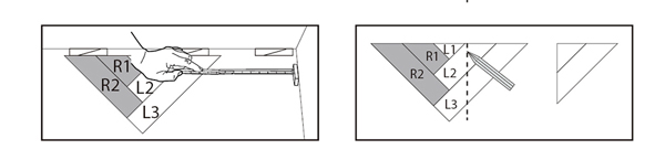
METHOD 2 – FISHBONE DIAGONAL PATTERN
– Using a pencil, a string and a ruler, draw a line at 45° that will be used to align the pattern according to the image. You can then start staggering your spacers across your wall, leaving a 1/4” / 6 mm expansion gap with the wall.
– Start from the left corner opposite from the door. Use an “L” marked plank first and put the tongue sides against the wall. Then take your 2nd plank (marked “R”) and place it perpendicularly to the 1st (Refer to the clicking tips on the bottom of the page). For the 3rd and 4th plank, refer to the cutting tips below. Continue the installation according to the sequence.
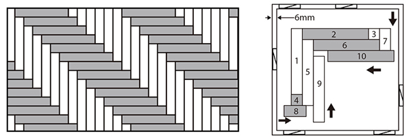
This sequence is given as an example, it will depend on the shape of the room. The important is to always start with the planks placed against the walls.
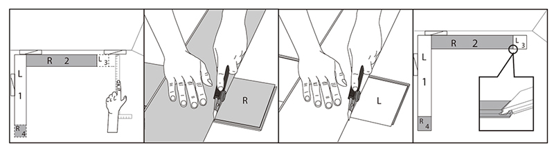
CUTTING TIPS
To install the 3rd (L), 4th (R) and any other plank that will have the short side against the wall, measure the length of the plank to fit and cut accordingly. Make sure you use the correct side of the plank (see images below).
METHOD 3 – FISHBONE PATTERN
– At first, follow the cutting template on the inside of your box to cut the 5 pieces (L1, L2, L3, R1, R2) needed for one starting set. You will need a total of 5 planks in order to make the required 5 starting set pieces (L1, L2, L3, R1, R2). You won’t be able to use offcuts of the same planks within one set. Align the first starting set with a chalk line going through the center line of the room (to center the installation, make sure the line goes through the tip of the pattern). Always leave a 1/4” / 6 mm expansion gap with the wall.
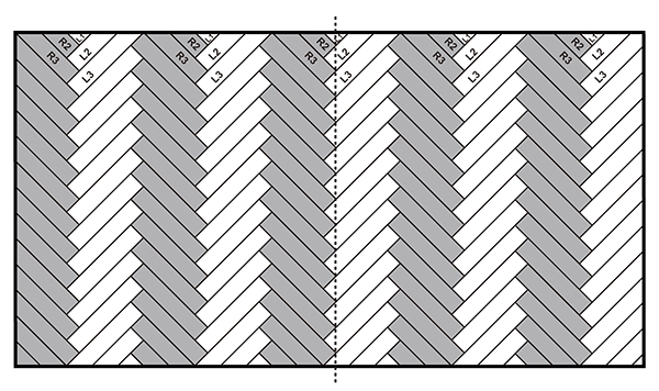
ONE STARTING SET
– Measure how many starting sets you will need based on the width of the room. You can connect the starting sets with one full plank.
– When you reach the walls on both sides, measure the distance between the wall and the closest starting set. Assemble a new set, mark the measured distance on it, cut the planks (the set can be disassembled for this) and install the planks in the gap.
Continue this pattern until the room is entirely covered.
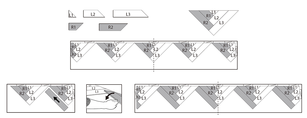
METHOD 4 – DOUBLE FISHBONE PATTERN
![]()
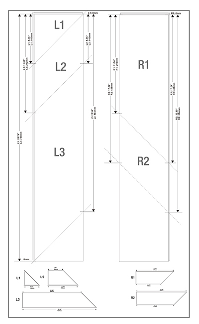
– For the double fishbone pattern, the cuts are different than what is indicated in the template inside of the box. Use measurements in below table to cut the 5 pieces (L1, L2, L3, R1, R2) of the starting set to the right size.
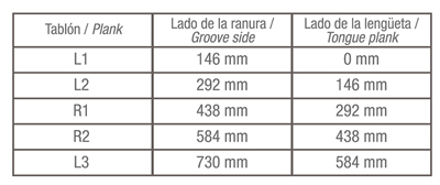
You will need a total of 5 planks in order to make the required 5 starting set pieces (L1, L2, L3, R1, R2). You won’t be able to use offcuts of the same planks within one set. Align the first starting set with a chalk line going through the center line of the room (to center the installation, make sure the line goes through the tip of the pattern). Always leave a 1/4” / 6 mm expansion gap with the wall.
ONE STARTING SET
– Measure how many starting sets you will need based on the width of the room. You can connect the starting sets with one full plank.
When you reach the walls on both sides, measure the distance between the wall and the closest starting set. Assemble a new set, mark the measured distance on it, cut the planks (the set can be disassembled for this) and install the planks in the gap.
Continue this pattern until the room is entirely covered.
DISASSEMBLING
To disassemble, simply lift the planks one by one following the opposite sequence as the installation.
BATHROOM INSTALLATION (GAP 10mm.)
With preexisting wall tiles
Leave 10 mm. expansion joint, fill with silicone and cover with a scotch molding.
With new wall tiles
Lay the wall tiles at a height or 6 mm. Also place 10 mm perimeter gasket between wall and C&F. Fill the gap with silicone and place the board under the tile. Grout.
SPECIAL PIECES
FLEXI PROFILE
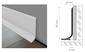
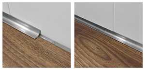
Flexi is a profile made of semiflexible PVC intended to be placed as a skirting in all kind of walls. It combines the excellent properties of rigid PVC with the appropriate degree of flexibility, which allows its installation in irregular walls or smooth curves. Its geometry, which ends with a smooth curve, makes easier the cleaning, avoiding the accumulation of germ. Also useful to cover the typical expansion joints in perimeters. Easy to install, glued to the wall with contact glue or adhesive for pvc, laying on C&F without pressing it. This profile is perfect for new or reform works and also for projects.
INSTALLATION
Flexi is a simple installation profile that does not require additional screws.
1. Clean the wall to install the RODAPIE FLEXI and check the profile.
2. Apply part of the adhesive to the wall. Then, apply part of the adhesive on the rear of the profile. You can use contact glue or mounting adhesives. Be sure the adhesive is appropriate for gluing PVC.
3. Glue the profile to the wall pressing to get an optimal adhesion. The lower ending (ESCOCIA) should delicately lean on the click&floor pieces without pressing them, to allow them freely shifting in the 6mm joint.
4. Clean the possible adhesive leftover and let dry.Each adhesive has its own features. Be sure you follow the instructions of the manufacturer in each case.
CLEANING AND MAINTENANCE
The cleaning can be done with water and detergent or specific cleaner diluted. The correct use of bleach or stronger cleaners on the market do not affect PVC. In case of doubt, always use the cleaners diluted and do a test on a small area.
It is not recommended using chromic acid, sulfuric acid or organic solvents as ethyl acetate, acetone or toluene.
PERFIL T
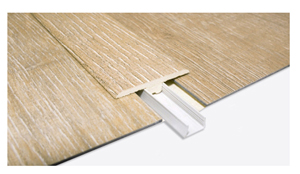
For surfaces over 400sqm, over 20m long or in the case of a surface where there has to be a transition from Click&Floor to a different floor tile, we recommend using T profiles taking care of the expansion joints (same joint that the perimeter joint)
STEPS
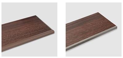
In the market there are specific solutions for SPC vinyl steps, such as those of the Schluter brand.